NEXT-LEVEL WATER TREATMENT
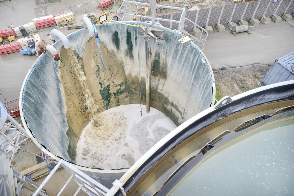
The HS2 site at West Ruislip in West London is huge. The view from the top of the decanter tower which is part of the project’s Wastewater Treatment Plant (WWTP) gives a hint of some of the activities underway. The new Northolt Tunnel portal is just visible, ahead are the huge conveyors that carry spoil away and, further away, there are piles of precast tunnel segments that are delivered in the night by rail.
Although not visible from here, Skanska Costain Strabag (SCS)–the joint-venture commissioned with the tunnel construction–is busy above ground as well. As part of Lots S1 and S2 of the HS2, SCS is constructing bridges and other structures that will carry the high-speed line up to the cut-and-cover tunnels, where it dives underground.
All this activity means that this WWTP has a lot of work to do. As well as processing the wastewater from the two EPB shields, the plant has to process wastewater from the many concreting and washing activities.
The plant’s capacity is 150 m3/hour. A sister plant will join it later this year, when excavation of the cross passages between the two main tunnels begins. It will have an even higher capacity of 250 m3/hour.
Most of the treated water that flows out of this plant will be reused, sent back underground to feed the TBMs processes. However, the plant must also be able to deliver water that meets stringent standards set by the UK’s Environment Agency, since the treated water overcapacity could be discharged into the environment to the River Thames.
Regulations around water quality are becoming more stringent in many countries, says Gino Vogt, Head of Herrenknecht Separations, who shows us round the plant. “A few years ago, a settlement pond might have been enough for a civil engineering site, but now we really need these plants, and they need the flexibility and efficiency to treat a variety of pollutants, depending on how site activities vary and also what is in the ground.”
For SCS tunnel and plant manager Francesco Giampietro, having one supplier for the TBM and for the WWTPs makes life easier. “Removing an interface has advantages for us,” says Giampietro. “It makes the design process smoother, and it means we can be more efficient in dimensioning and installing the plant.”
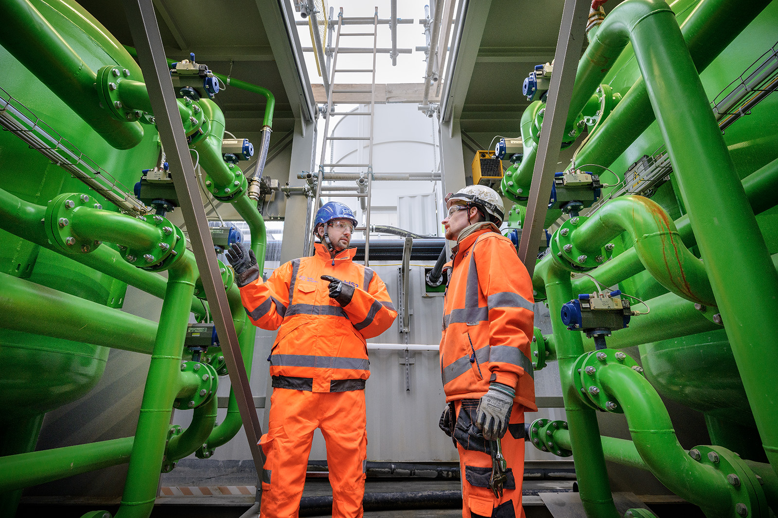
Thanks to the containerized and modular approach, the WWTP offers flexibility to adjust to changing requirements on the job site.
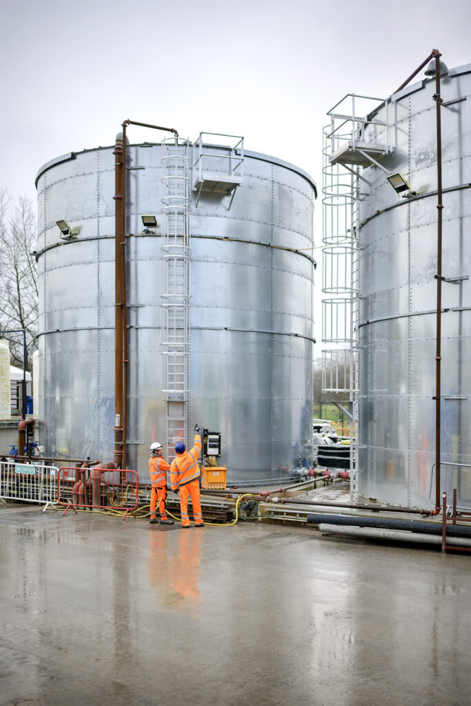
This construction site treatment process starts with three huge settlement ponds around 1000 m3 provided by SCS, which—from a distance—could be mistaken for rectangular swimming pools. On the day of our tour, two of the three tanks which should buffer over productivities and collect surface water are empty, and the soil sediment is being excavated out.
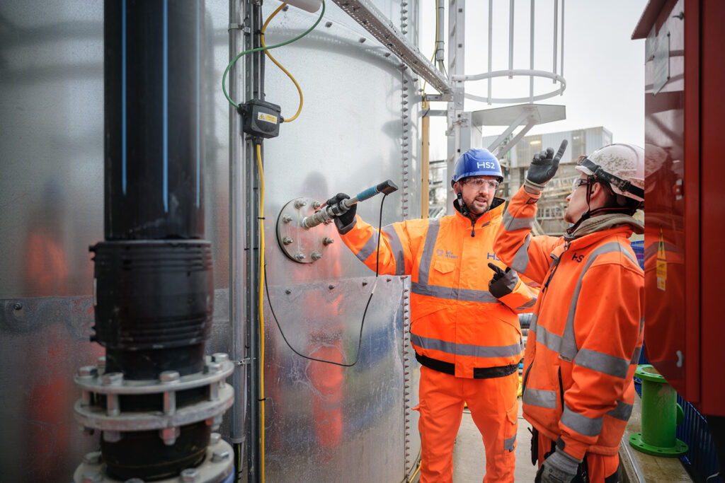
The pond nearest the WWTP is in action, and from here water feeds through a pipe into the plant’s incoming buffer silo tank. In parallel with that pipe are two others, one from each of the two TBMs.
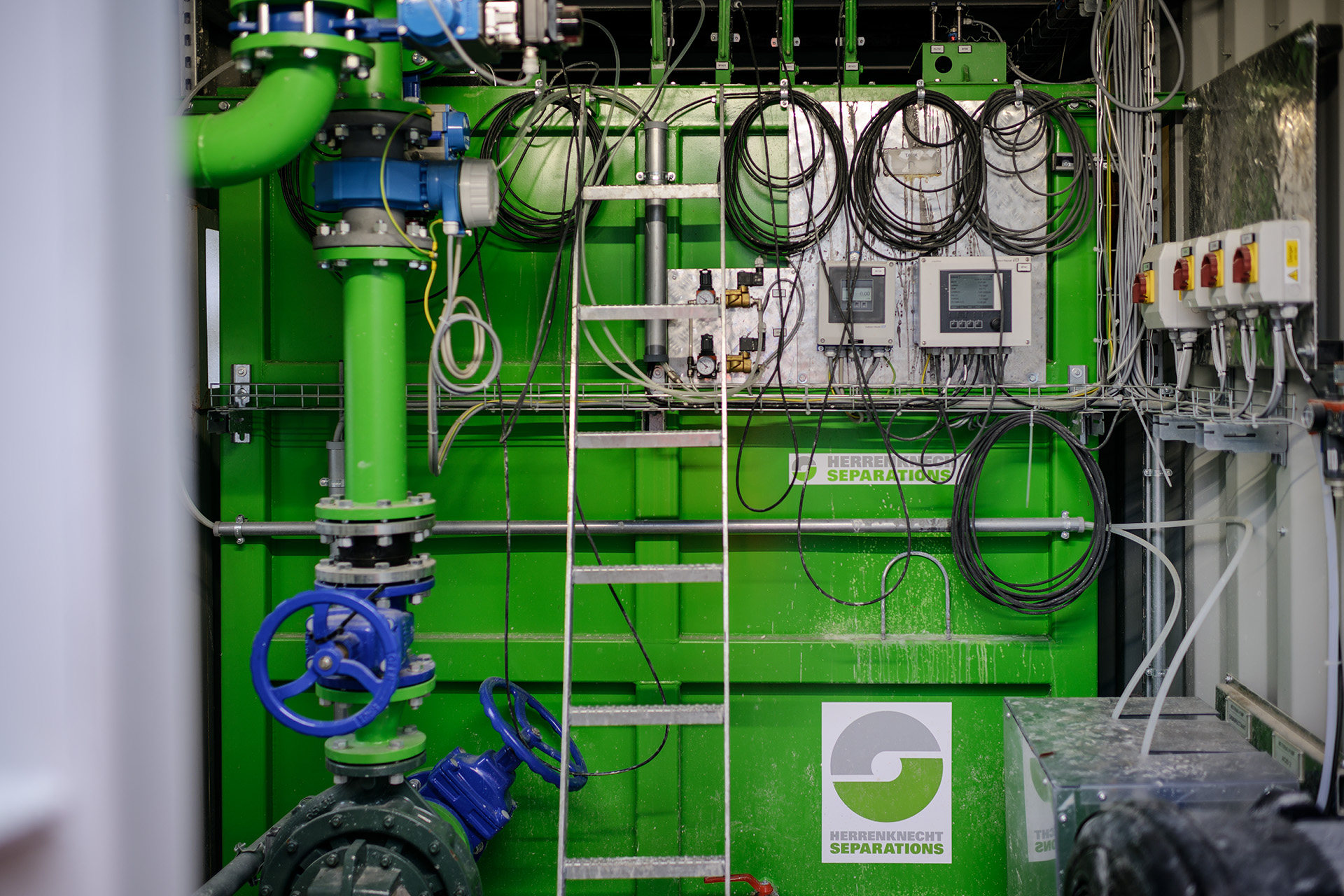
The buffer tank holds around 250 m3 of liquid and is equipped with an agitator which stirs up the water to ensure that it is homogeneous. If the consistency of the wastewater were to vary too much, the chemical dosing later on in the process would have to change too often, yielding inconsistent results. Sensors in the tank measure turbidity, pH and electrical conductivity—to indicate whether metals or salts are present.
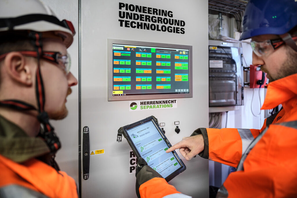
Virtual preview
Indicating the panel and digitized process, Keiton Wall, the SCS operator in charge explains some of the things that he and his colleagues keep an eye on: “We have to check the pH as it’s going through, for example. If that’s off, the water will keep circling until it’s in the target range,” he says. “We also look at turbidity as it influences several process steps, like the filter press and check that the water’s going through quick enough, otherwise there could be blockages.”
On the day of the visit, there is only 0.539 grams of solid per liter in the wastewater being treated, which is quite low. This plant can handle up to 40 grams per liter. By the time it exits, there are 10.02 milligrams per liter in the water. Meanwhile, the pH has fallen from a very alkali 14 at entry to a neutral 7.5 at exit.
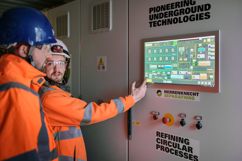
Like almost all the elements of this plant, the control room is housed in a shipping container. Keiton Wall, one of three technicians employed by SCS who work on the plant, shows us round virtually, by way of the display screen.
Most days, Wall and his colleague have to carry out regular checks on the plant. The Maintenance.ON module installed on a tablet tells them this.
Maintenance reminders
Herrenknecht.Connected is a platform which collects, manages, and visualizes data from the WWTPs, TBMs, and other equipment in Herrenknecht’s scope. Through tailored dashboards and reports, SCS uses the platform to monitor progress and keep various stakeholders informed of what is happening on site. On this project, SCS is also managing other equipment, that is not supplied by Herrenknecht, through Maintenance.ON, a part of the Herrenknecht.Connected platform.
Later in the day, Wall will carry out the prescribed tasks, report that they have been completed, and add any photo and any notes that are required. Data is fed into the system using a tablet.
A cocktail of chemicals
From the initial buffer tank, the wastewater heads down into a smaller, 10 m3 tank to receive its cocktail of chemicals. These will vary from site to site and even over the lifetime of a project. For instance, the concreting activities at West Ruislip have pushed up the chrome content of the water above what was expected, which means the treatment process and chemicals dosing have to be optimized.
“As, typically, sites cannot guarantee incoming values due to varying activities, we have to adjust the plants regularly, which is why you need flexibility,” explains Vogt. “With our containerized and modular approach, you can add things in easily, and we can provide support via remote control.”
Among the chemicals being added into the water, there is a specific and tested flocculant which makes the suspended solid particles in the water clump together and is automatically dispensed. The plant automatically adjusts the dispensing rate, according to what the wastewater at the time requires.
The heart and brain
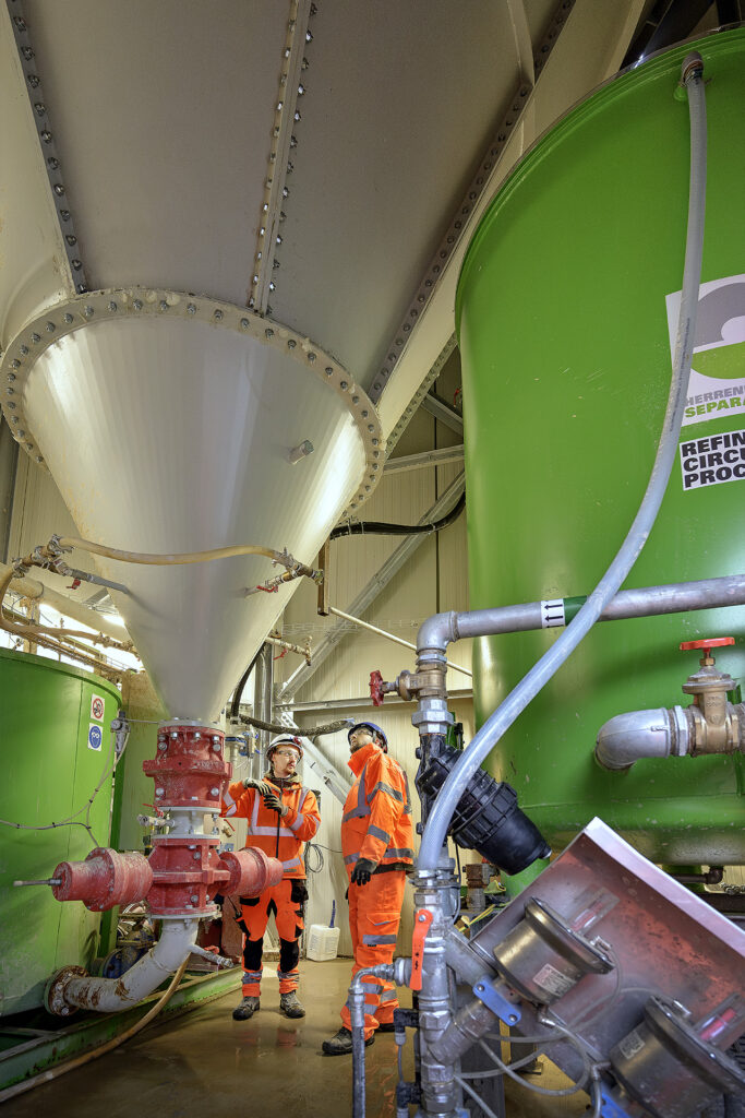
The linear decanter or thickener, with its access ladder and platform around its upper perimeter is the one that provides views over the site. Looking down into the top of the decanter, there is a view of a central cone, tapering as it descends to the bottom of the tank.
The solids reacted with the flocculant agent settle down into the cone, while cleaner water spills over the top rim. A slow-moving scraper clears the walls of the cone and homogenizes the settlement.
Inside the structure at the base of the decanter is what Vogt calls the “heart and brain” of the plant. Walking through, one’s gaze is drawn to a glass-fronted cabinet which seems to contain a chemistry experiment with a glowing tube at its centre: The Floccmaster Control Station.
It measures the efficiency and reaction of flocculation on the solids in the wastewater by passing an optical sensor through the tube and the material it contains while flow stops for a few seconds, explains Vogt: “This determines whether you can send it further to feed the filter press with a good reaction or whether it has to be treated again with adjusted parameters.”
With a special robot
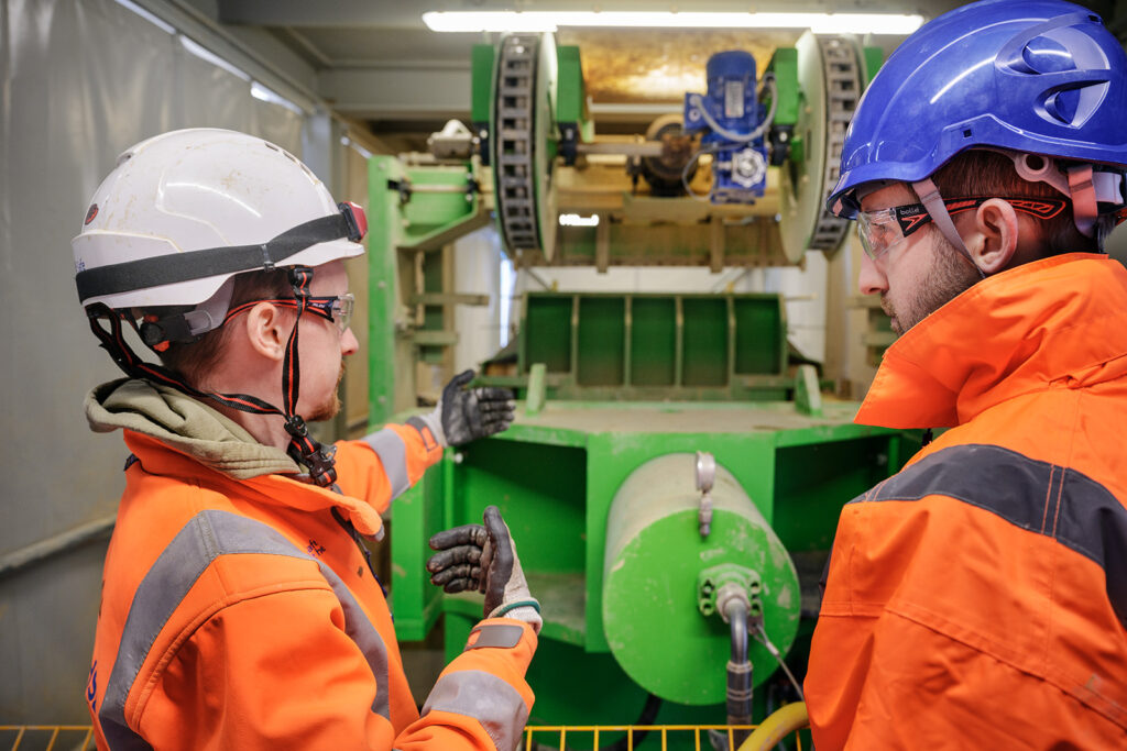
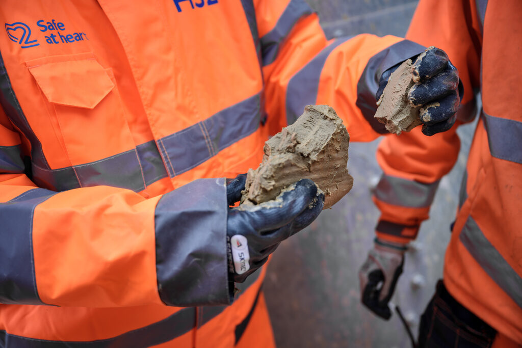
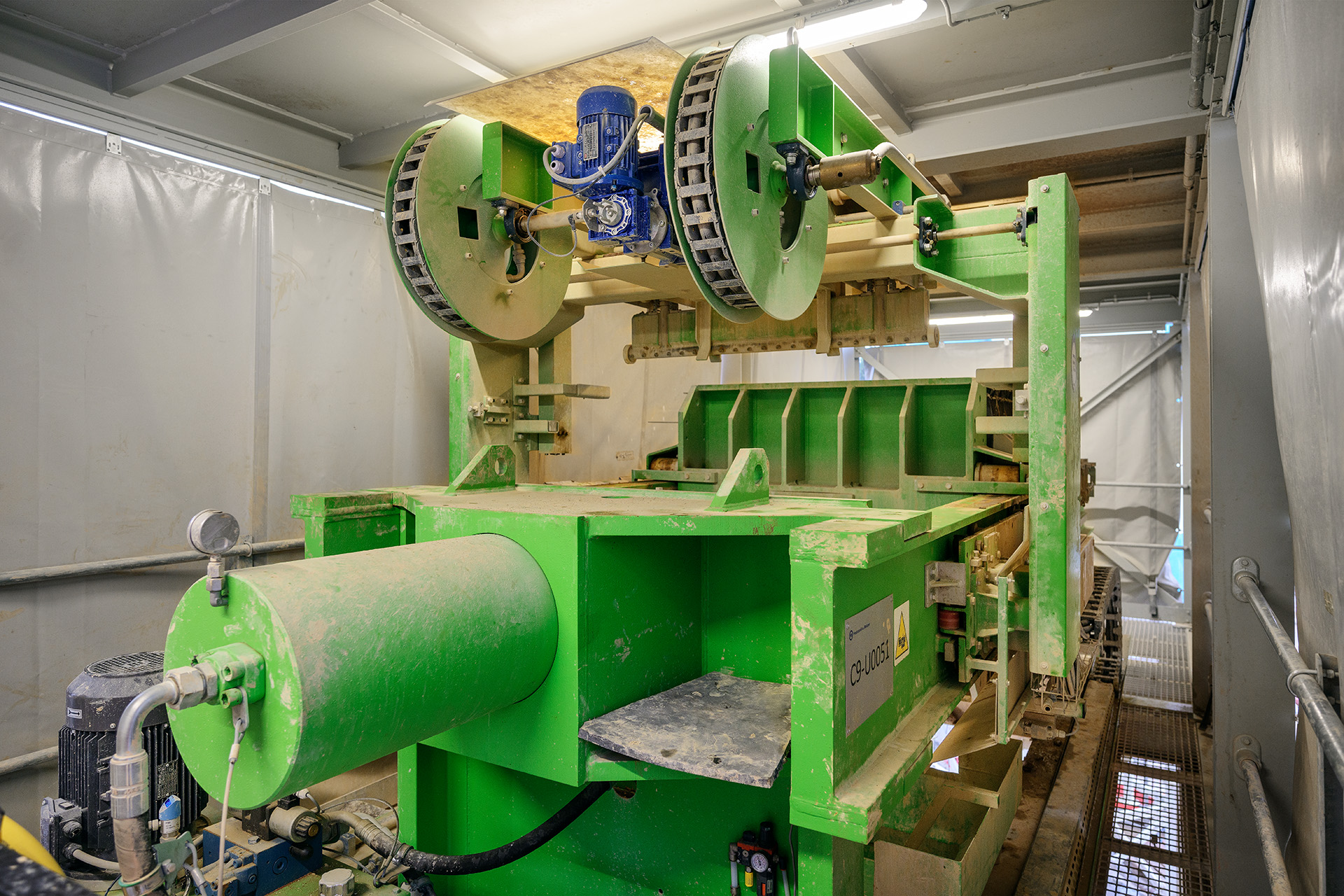
The filter press dewaters and takes out the solids extracted from the wastewater through the decanter and presses them through a filter cloth between vertical chamber plates to create thin solid ‘cakes’ which drop down to a muck storage area below.
These are then loaded onto lorries to be taken to a designated area nearby which will later be landscaped. This filter press has its own automatic cleaning robot that washes the cloths at least once a day to extend their lifetime.
Refining with filters
While the solids are being pressed into cakes, the water must go through three further filters to achieve the target quality. First it heads up through a coalescing filter taking out hydrocarbons housed in a container at a higher level and then heads down to the sand and activated carbon filters which are housed in two side-by-side containers.
Vogt pulls back plastic ‘curtains’ from the sides of the two containers to reveal a series of tanks which contain the filter materials. “If the requirement for remaining solids is for less than 100 milligrams in the outlet, you need the sand and activated carbon filter,” he explains. “This sand filter is a specific type with different sand grain sizes. The water flows from the bottom to the top through the different grain sizes so that some of the pollutants remain in the sand. Then it goes through the carbon activated filter using the same principle.” The plant automatically back flushes the filters when the set maximum pressure level is reached to extend their lives to a maximum.
Reuse or back to the beginning
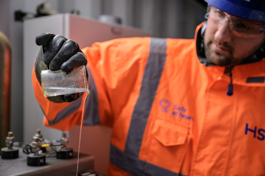
Having passed through the filters, the water goes into a small tank inside the container where sensors measure the same parameters as those in the incoming tank to compare overall efficiency. The water at this point—and at various other points along the process—will be sampled and tested on site and in an off-site laboratory for calibration and additional control.
From here, the water can head in three directions. If it has not reached the required specification, it will be automatically sent round the processing loop again. Or it can be discharged to the sewer system and on to the river, providing the high standards required by the Environment Agency are met. Or, as is happening currently on this project to save costs, the water goes back to the TBMs and is reused. And so the whole cycle begins again.
| Project data | |
|---|---|
| Client | High Speed 2 Ltd. (HS2) |
| Customer | Skanska Costain Strabag (SCS) JV |
| Location | London, West Ruislip, United Kingdom |
| Tunnel operations | Since 2023 |
| Application | Railway |
| Geology | Clay, Limestone, Chalk (mixed) |
| Tunnelling length | Approx. 15,757 m |
| Machine data | 2x EPB Shield Diameter: 9,829 mm Northolt Tunnel West 2x Wastewater Treatment Plants Treatment capacity: 150 m³/h 1x Cooling plant 1x Batching plant |